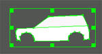
AC3D Tutorial - Constructing a textured car body

Creating one side of the car

Preparation:

The gif image (available at the bottom of this page) was set as a background image on each of the 2D windows.

'Nearsnap' was switched on. (toggle at the bottom of the AC3D window). This 'snaps' new points to the same position as existing points. This helps line up the points where the top and bottom polygon join.

The polygons are drawn in the Side view.

Process:

Two separate polygons are used because the top polygon will be used to represent the side windows (which will tilt inwards) and a polygon must have all of its points on the same plane for it to be valid.

Using the background image as a guide ensures that the polygons being made remain in the correct proportion in relation to the texture image.

At this point - after selecting all, Object->merge has been used to put all selected surfaces into the same object (not shown in movie).


Play movie (500k)

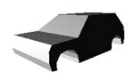
Extruding the 2D side to make a 3D car body

After selecting both polygons, they are moved to the edge of the rear view image and extruded to cover it. This ensures that the front/rear views of the car will be the correct width for the image. The control key has been held down when the object is dragged - this ensures that it is extruded at 90 degrees. Not holding down the control key whilst dragging may result in a skewed shape.

After the extrusion, vertex select-mode is set and the roof vertices are moved inwards to give the car's side windows a slight slope, and to line up the rear window shape with the texture image.


Play movie (800k)

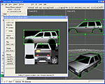
Using the Texture Coordinate Editor (TCE)to position the texture on the body

The object is set to have the same texture image that was used as the background image. In this case, it was already loaded, so 'rover.gif' appeared in the Object->Texture menu.

The texture coordinate editor (TCE) is accessed from the Tools menu. It allows you to position texture coordinates, sometimes know as UV's.

After the texture is first applied, you can see that the texture image is not correctly mapped on the whole object. To map the surfaces, one or more surfaces is selected and then representations of these are dragged/sized/rotated over the image in the TCE. This specifies where on the image, each vertex will take its position on the picture.

(In Surface select-mode) The whole shape is selected in the main AC3D window and the surfaces appear in the TCE. These are then selected in the TCE by dragging a rectangle over them. The TCE Remap->side function is used to 'project' a mapping of the image over the selected surfaces. This causes a stretched image of the car's side to appear in the TCE - this is then scaled so that it fits over the image. Notice how (in the 3D window) the texture is now lined up on the sides of the car.

A similar process is then carried out on the remaining surfaces, in three groups. The roof/windscreen/hood, the front and the rear. The surfaces are selected in the 3D window. This is done by holding the control key and clicking on each surface. Additionally, holding the shift key allows extra surfaces to be added to the current selection. Note that for the car's front, the image first appears mirrored in the 3D window i.e. the 'Land Rover' text is reversed. The TCE's Flip->horiz is used to flip the texture coordinates so that the text is the correct way.


Play movie (3.8 meg)


This is the texture image used in this movie. Note that this is a gif file which offers less quality than a jpeg due to the limited range of colors available. 


to save this image, right click on it and select 'save as...'.

Points to note about this tutorial

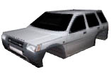
More time can be taken when creating the car sides to form more polygons (thus allowing the sides of the car to be adjusted and have a curve incorporated). The wheel arches are also not very detailed - more vertices could be inserted.

When extruding, the number of segments is set to one. Higher values would allow more of a curved shape to be added to the top, front and rear of the car.( Extra surfaces could be inserted to the current model by selecting those surfaces and using Surface->Divide. Moving the new points would add more of a 'curve' the the vehicles shape.)

The two polygons that are initially created are seperate objects and have been merged (Object->merge),then the object vertices have been shared (by using object->optimize vertices). This puts all the surfaces into a single object and ensures that there were no duplicated vertices.

The bottom surfaces of the car have not been mapped in this example. There are also other unused parts of the texture map e.g. mirrors and wheels. Wheels can be made simply by extruding a disk (or an Ellipse set to surface type 'Poly').