Woody's AC3D Tire With Tread Tutorial
This is a tutorial originally posted by Woody in the AC3D Tutorial/Resources forum
back in 2003. It has been reposted here to save the images and archive files that accompanied
the original post. With the exception of redirected links to the zip files at the start
of the tutorial (noted by "(NOTE: Redirected-
original link dead)") and the removal of posts/graphics which
were not part of the tutorial body, the post is as it originally appeared.
 |
-WOODY-
Joined: 16 Sep 2003
Posts: 65
|
| Posted: Wed Nov 12, 2003
9:03 pm Post subject:
Re: Tire with tread tutorial ( done ) |
|
|
Well I had to delete all my
other stuff to make room for this, so here it goes.
Tutorial: How to make a tire with real modeled tread
Materials needed: AC3D ( of course ), tire_blueprint.zip, and
tire_texture.zip ( optional )
You can download the files here:
tire_blueprint http://home.earthlink.net/~slwoodgraphics/tire_blueprint.zip
(NOTE: Redirected - original link dead)
tire_texture http://home.earthlink.net/~slwoodgraphics/tire_texture.zip
(NOTE: Redirected - original link dead)
If for some reason you no longer have access to download the files
or you see nothing but X's where the photos should be, it's because
I have limited bandwidth. You'll have to wait till next month
to gain access to it again. Sorry
To begin:
Begin a new scene within AC3D and load your front and side Orth
views with the "tire_blueprint.jpg" image. For your pan view,
load the "tread_pattern.jpg" image.

( Pic 1 )
With your line tool and in side view, create an arch that follows
the front view cut-a-way profile up to the blue line. Make sure
that you only have one vertice on each side of the blue line then
follow the guide down to the other side. To make sure that the
line that follows the blue line is level, you can use the "grid
snap" feature or just select the 2 vertices at each end and scale
to "0" on the "Y" axis.

( Pic 2 )
After that is created, select the object then in the control panel,
hit "move to" and make sure that the coordinance is set to 0,
0, 0. With the object still selected, go into vertex selection
mode and control+click ( to only move along one axis ) and drag
the selection back up until the top is level with the first blue
line on your image guide. This is to insure that the object's
center matches that of the tire's center.

( Pic 3 )
Now go into front view and with the oject selected, go into your
object menu, then "Revolve" and enter the following settings:
degrees: 360
axis: Z
segments: 40
offset: 0.0
Now hit Revolve.
Making 40 segments will ensure that our object will be smooth
without having to subdivide afterwards which will let us keep
our sharp tread edges.

( Pic 4 )
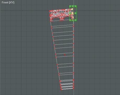
While still in front view, select all vertices except for 2 colums
at the top and delete which will leave us with a wedge shape.
Don't forget to go to "object" and "optimize vertices" and "optimize
surfaces" afterward.

( Pic 5 )
When that's done, select the object and rotate along the "Z" axis
at 4.5 degrees which will make the top of our wedge level and
flat. After that's done, click on "hide" to get it out of our
way so we can work on the tread pattern.

( Pic 6 )
Now go into pan view and create a mesh that is 1 colum wide by
12 rows deep and scale to fit the image's width and half the image's
depth. Go into vertex selection mode and and select each vertex
on either side of a single line then contol+click and drag the
line into position. Make sure that there is a line that is on
top of each of the yellow dotted lines and that there is a line
that intersects at each point where a tread pattern begins and
ends at the boarder's edge. The image isn't perfect so just use
your best judgement. Make sure that the very bottom line is at
the half way point of the tread image.

( Pic 7 )
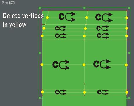
In surface selection mode, select the first top 2 rows of surfaces
and divide once. Combine the doubled rows of surfaces in each
colum and delete the leftover vertices until a single division
line exists.

( Pic 8 )
Select the vertical vertices of the single line and control+click
and drag the line over to the left side of the pattern to line
up with the black edge in the upper lefthand corner of the pattern.
Snap the bottom 3rd vertice to the vertice to the left on the
border of the image. When sapping the line vertices to the border
vertices, make sure you do the following...

( Pic 9 )First select the border vertice and in vertex selection
mode, hit the ">" button to enter in the location coordinance
in the control panel. Select the other vertice that is to be moved
then hit the "move to" button to put it in the exact same position
as the other vertice. After that, drag a selection box over both
vertices then hit "control+T" to snap them both together. Don't
forget to select the object then in the menu options select "optomize
vertices" afterward. Do this every time you snap vertices together
and optimize afterward so you don't run into any problems.
( Pic 10 )
Now in surface selection mode, select the top 5 rows of surfaces
to the right of the line we just moved and divide once. Combine
the doubled rows of surfaces and delete the leftover vertices.

( Pic 11 )
Move the resulting single line by control+click and dragging the
vertices to the left to line up with the second longer edge of
the black tread pattern.
( Pic 12 )
After that's done, select the upper 5 rows of surfaces to the
right of that line and divide once ( are you seeing the pattern?
). Combine faces and delete leftover vertices to get the single
line of division.

( Pic 13 )
Move the resulting single line over to the left and adjust to
fit the next black edge of the tread pattern.

( Pic 14 )
You guessed it, do the same thing again to the right of the line
by selecting the top 5 rows of surfaces then combining and then
deleting leftover vertices.

( Pic 15 )
Move the line to the next edge of the black pattern.

( Pic 16 )
Now select the 3rd, 4th, and 5th rows of surfaces from the top
and to the right of the single line and divide once.

( Pic 17 )
After combing surfaces and deleting vertices, adjust the resulting
line to match up with the edge of the black tread pattern and
snap the top vertice of the line to the outside boarder vertice
using the location and move technique. Be sure to optimise afterward.

( Pic 18 )
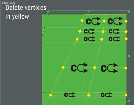
After completing the upper portion of the tread pattern, add one
vertice to each of the 4 lines indicated and in vertex selection
mode, select all at once and control+click and drag all of them
over slightly to the right to create a slight bend.
( Pic 19 )
In surface mode, select the 10th and 11th rows from the top and
divide once. Combine and delete as before.

( Pic 20 )
Move the resulting line over to the left to match the black edge
of the small pattern next to the boarder. Snap the top vertice
of the line to the one on the boarder and optimize.

( Pic 21 )
In surface mode, select the 9th, 10th, and 11th rows of surfaces
from the top and divide once. Do the same as before

( Pic 22 )
Move the line over and adjust and then snap the top vertice of
the line to the vertice on the boarder and optimize.

( Pic 23 )
Now select the 7th, 8th, 9th, 10th, and 11th rows of surfaces
from the top and divide once.

( Pic 24 )
Do the same with combining and deleting and adjust the single
line to the black edge of the pattern.

( Pic 25 )
Select the same number of rows to the right of the single line
and divide once.

( Pic 26 )
Repeat as before.

( Pic 27 )
This time select the 9th, 8th, and 7th rows of surfaces and divide.

( Pic 28 )
Adjust line over to the right and snap the bottom vertice to the
one on the boarder.

( Pic 29 )
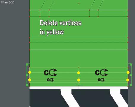
Now select the 7th and 8th row of surfaces to the right of the
line and divide once. Do the same as before.

( Pic 30 )
Now adjust as neccessary and snap the bottom vertices together.

( Pic 31 )
Well we're almost done with the tread part. In object selection
mode, select the top tread object and dupicate. Now rotate it
180 degrees on the "Y" axis and control+click and drag the object
downward to align it to the bottom part of the tread. Now merge
the 2 objects together, snap vertices, and optimize. After that,
combine the 2 adjoining surfaces together and delete the extra
vertices as shown.

( Pic 32 )
Now unhide your sidewall and delete the top surface.

( Pic 33 )
In pan view, select your tread and scale to size. Zoom in as close
as you can and size the tread to match up to the 4 corners of
the sidewall. Since we wont be subdividing the tire, there is
no need to add additional vertices to the sidewall edge to match
up with the tread when we go to merge and snap vertices together.
If you still want to subdivide your tire when you're done, then
at this point, add 3 additional vertices to the sidewall edge
and align them horizontally to match up with the 5 vertices in
the top and bottom of your tread. If you don't do this and then
subdivide, you'll end up with several open gaps in your tire.
If not, then just position the tread level and even with your
sidewall and merge. Snap vertices together and optimize.

( Pic 34 )
Now go into side view and contol+click and drag each vertice up
until they are even with the green line as shown.

( Pic 35 )
Now in surface mode, select all of the black area of the tread
and extrude upward to the red line. Flatten the edge of each side
by using the "move to" function with each vertice and optimize
vertices and surfaces afterward. Select the vertice edges of each
part of the tread and move it back toward itself to create a slight
taper. The 3 lines that you created following the yellow dotted
line on each side of the tread are now what make up your bend
in the tread. Adjust these lines to create the neccessary bend
and align the rest of the vertices so you don't see any curling
of the surfaces above or below your line.
( Pic 36 )
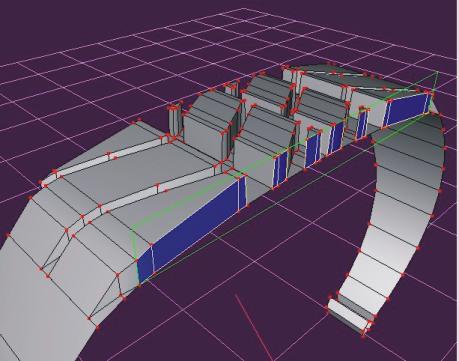
Now select the surfaces that are directly aligned to the outside
edge of your tread and sidewall ( shown in blue ) and delete.
Do this as well to the other side.
( Pic 37 )
In front view, rotate your object -4.5 degrees on the Z axis till
the right side of your object's vertices of the sidewall are vertical.
Now select the upper vertices in your tread that are not directly
aligned above the lower vertices and scale to "0" on the "X" axis
to straighten them. Now control+click and drag all of them at
once till they are directly aligned above the ones below them.
Don't mess at all with the vertices in your sidewall because if
your're off even slightly, it will make a big difference by the
time you multiply these sections a few times. Now rotate the object
the other direction in increments of 4.5 degrees till the other
side is vertical and repeat this process.

( Pic 38 )
Once that's finished, rotate the object the other direction till
the right side is vertical then duplicate. Rotate the duplicated
section the opposite direction till the mated halfs are vertical.
Now zoom in as close as you possibly can and align the objects
together till the vertices are right on top of each other. Now
select both halfs and merge objects together. With the merged
object still selected, go to vertex selection mode. In your vertex
menu, select "snap together by distance" ( trust me, this will
save you mountains of time ). In the box that pops up, input this
number "0.005" and then hit snap.
Once you do that, be sure to optimize your vertices afterward.
( Pic 39 )
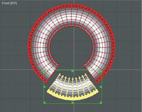
Repeat this process of duplicating, rotating then merging objects
till you end up with what you see here. Now you'll have to select
8 sections in surface mode and duplicate.
Rotate the last object in 4.5 degree increments to fit then position
and merge.
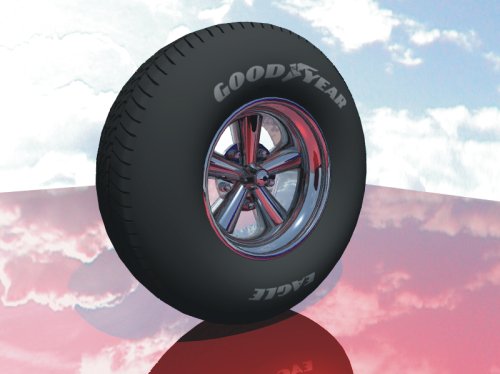
Now all you have to do is create a rim, maybe a nice tire texture,
and 32 pounds of air pressure and you're done.
 |
|
|
|